Tutorials in this section:
Just like the Resistor, the Capacitor, sometimes referred to as a Condenser, is a passive device. It is one of the three basic passive devices which include resistors, capacitors, and inductors.
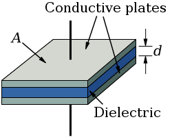
In its basic form, a capacitor consists of two conductive (metal) plates which are not connected or touch each other, but are electrically separated either by air or by some form of insulating material such as paper, mica, ceramic or plastic. This insulating material spans the entire area of the plates and is called a Dielectric.

The plates have terminals on each one for connection, and they don’t have to be flat, but could be formed as cylinders, spherical shapes, etc. For larger capacitor values, the "plates" may be strips of metal foil, sandwiched around a flexible insulating medium and rolled up for compactness. As long as there are two conductive areas separated by a dielectric, it could be considered a capacitor.
When a voltage is applied to the two terminals of a capacitor, there is a rapid inrush of current that is similar to short-circuiting a battery. However, this is only a short pulse of current that allows a certain amount of charge to build up across the plates because of the interaction of the electric field generated between the plates.
The capacitor operates in a manner very similar to a battery. The capacitor can be “charged” by applying voltage to it through a current limiting resistor. When the voltage is then removed, a capacitor will hold the charge indefinitely unless there is a resistive load between the terminals.
As voltage is applied to the terminals, a concentrated field flux is generated between the plates, which allows a significant difference of charge (free electrons) to develop between the two plates. Capacitors store the potential energy of accumulated charge (or electrons) in the form of an electric field between the plates.
This field is sometimes called an "electrostatic field". Energy storage in a capacitor is a function of the voltage between the plates, and has nothing to do with current, because current can’t flow in a dielectric, as this is where the energy is stored. This behavior is quite different than resistors, which dissipate energy in the form of heat. Capacitors don’t dissipate any energy except through a small leakage current through the dielectric, which is a resistive element.
The currents in a capacitor are mainly for charging and discharging the capacitor by increasing or decreasing the voltage across its terminals. As energy is stored by increasing the voltage, that same energy is released through resistive loads as the voltage is decreased of removed.
The ability of a capacitor to store charge on its plates in the form of an electrostatic field as a function of voltage is called the Capacitance of the capacitor.
Capacitance is also is also a measure of the ability to resist changes in the voltage applied. In other words, it is a tendency to try to maintain voltage at a constant level. Capacitance is measured in Farads, where one Farad is defined as the capacitance when one Coulomb is stored on the plates when one volt is applied. This is a very large unit, and not very practical, so micro-Farad (uF), nano-Farad (nF) and pico-Farad (pF, 10-12 Farads) are generally used instead as a measure of capacitance.
When a capacitor has stored energy there is a charge built up on both plates, and these charges are equal but with opposite polarity. The capacitor's capacitance (C) is a measure of the amount of charge (Q) stored on each plate for a given potential difference or voltage (V) which appears between the plates:
C = Q / V
The amount of capacitance within a capacitor is a function three basic dimensions of the capacitor’s construction. These factors will determine capacitance by affecting how much electric charge can be stored on the two plates for a given voltage as the dimension is varied.
Plate area: The amount of capacitance is directly proportional to plate area, so that a larger plate are means higher capacitance, and less plate area means less. The reasoning for this is that the amount of field flux (charge collected on the plates) generated increases with plate size for a given voltage between the plates, as this provides more area for charge to build up.
Plate spacing: The amount of capacitance is inversely proportional to plate spacing, so wide spacing gives less capacitance, while closer plate spacing gives greater capacitance. This is because the field flux is proportional to the voltage across the capacitor divided by the distance between the plates. A greater field flux will allow more charge to build up on the plates, which results in a larger capacitance value.
Dielectric material: The larger the permittivity of the dielectric, the larger the capacitance. And less permittivity dielectric allows less capacitance. The permittivity of a dielectric in a capacitor is the relation between the field flux and the voltage applied, which is very similar to the relation between current and voltage in a resistor (conductivity). Some materials have greater permittivity than others, which allows more field flux to be generated for a given amount of field force (applied voltage). This will then allow more capacitance with the given plate dimensions, and allow more charge to collect on the plates. More will be explained on this later.
These three factors can be combined into one equation which will provide an approximation of capacitance: C = εA/d, where ε =Permittivity of dielectric, A=area of the plate in square meters, and d=distance between plates in meters.
There is a definite mathematical relationship between voltage and current for a capacitor, even as there is a relationship between voltage and current for a resistor.
For a resistor, this is essentially a linear relationship; whereas in a capacitor, it’s not. There is no “resistance” or “conductivity” in a capacitor like there is in a resistor.
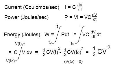
In a capacitor, the current is proportional to the change in the voltage applied instead of the voltage itself. So for a resistor, the equation would be I = V/R, while for a capacitor, the equation becomes: I = C x dV/dt, where I = Current through the capacitor, C = Capacitance in Farads, dV/dt = Rate of voltage change (volts per second).
The “time” variable becomes an important factor for capacitors, while it has no effect on resistors. This equation can be derived from the basic equation C = Q/V by assuming that I = dQ/dt, so C x dV = dQ, and C x dV/dt = dQ/dt, which reduces to I = C x dV/dt.
The amount of energy stored within the electrostatic field or a capacitor is derived below. The power (P) is derived from the equation for current, and the power integrated over a time when voltage is applied to build up charge yields the energy stored in the electrostatic field.

The same result would be obtained if the energy was derived from the equation C = Q/V, and integrating over charge instead of voltage.
Whenever an electric voltage exists between two separated conductors, an electric field is present within the space between those conductors which stores the potential energy. This field doesn’t even have to have any mass, and could even be empty vacuum.
Electric fields have two units of measure: a field force and a field flux. Field force and flux are roughly analogous to voltage and current through a conductor, respectively.
The space between the two conductors has a certain amount of opposition to the field flux as the field force is applied, similar to the opposition a resistor has to current (flow of electrons) when voltage is applied. The amount of field flux that develops in a material is proportional to the amount of field force applied, divided by the amount of opposition to flux, similar to the I = V/R equation for a resistor, although flux can even exist in empty space, and currents must have a conductive material to pass through.
Just as the type of conducting material determines its resistance to electric current in a resistor, the type of insulating material separating two conductors determines the specific opposition to field flux.
The value of permittivity used in the above equation (C = εA/d) is a measure of this opposition to field flux. The resistance value of a resistor is calculated in the same way from a value for conductivity. For empty space (vacuum), the value for permittivity (ε) is 8.84 x 10⁻¹² F/m. A vacuum would not be practical for use as a dielectric, so other insulating materials with a relatively high permittivity are used instead. Some of the more common materials are air, paper, polyester, polypropylene, Mylar, ceramic, glass, oil, and others.
The factor by which the dielectric material, or insulator, increases the capacitance of the capacitor compared to a pure vacuum is called the Dielectric Constant. This is a dimensionless quantity, since it is relative to a vacuum, and the dielectric constant for a few common materials would be: Pure Vacuum = 1.0000, Air = 1.0005, Paper = 2.5 to 3.5, Glass = 3 to 10, Mica = 5 to 7, and Metal Oxide Powders = 6 to 20.
Since a capacitor can store electricity, or electrical energy, and resist voltage change, it can perform many useful functions in variety of circuits. Its main use is as a filter, as it tends to pass alternating current (AC) and block direct current (DC). From the current equation, it is easily shown that for AC circuits (sinusoidal waveforms), there is a phase shift, as the voltage "lags" the current by 90 degrees. It can be shown that a capacitor has an impedance on the imaginary axis on a complex number plane, while a resistor has an impedance along the real axis.
The next article on capacitors will discuss the various types of capacitors and what kinds of circuits they are typically used for.
