EMBEDDED ADVENTURES: CONNECT THE WORLD AROUND YOU
Tutorials in this section:
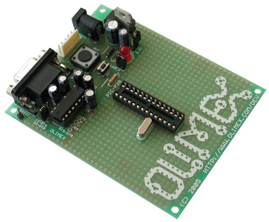
In describing how to get microcontrollers working in real life, we had to be a hardware platform to describe. In the first instance, we’ll talk about the the Olimex PIC-P28 board. There are lots of other platforms you could use instead, however.
By way of background, there are a few different ways of getting software into a microcontroller.
ICSP
In Circuit Serial Programming (ICSP) is the microcontroller’s fundamental way of loading software. It can use up to 6 pins:
Vcc – Positive supply (5v)
Gnd – Supply ground
PGD – Program data
PGC – Program clock
Vpp – Programming voltage
PGM – Low voltage programming
To program using ICSP, a high voltage (between 9v and 12v, depending on the PIC) is delivered to Vpp. At that point the PIC understands it is in programming mode. Then the PGD and PGC pins are used to program the internal flash memory of the microcontroller.
This mode of programming is always available. There is another mode that doesn’t require a high voltage on Vpp – instead, a normal supply level voltage is provided on the PGM pin. This is called LVP or Low Voltage Programming. Of course, in order to understand that programming is required, the PGM pin is therefore unavailable for any other uses.
The Pickit2 is a good example of an ICSP programmer. There are many others.
Bootloading
Modern PICs have the ability to read and write to their own flash memory. This makes it possible to use what is known as a “bootloader”. This is a piece of software that remains in the PIC flash and has the ability to update the rest of the flash memory with your program. Of course, you need to get the bootloader into the PIC somehow – so that needs to be done using ICSP.
All the PICs from Embedded Adventures come with the Boostbloader pre-loaded, so you’re good to go without requiring any ICSP programming in the first instance. There are times when you’re going to want to replace the bootloader though, so we’ll cover ICSP programming in another tutorial.
Getting ready
For this tutorial, you’ll need:
- An Olimex PIC-P28 platform
- A PIC18F2620 28 pin DIP microcontroller
- A 10Mhz crystal
- Male header + Female jumper wires
- USB to RS-232 connector
- (optional) Pickit2 programmer
Preparation
We need to connect the RS-232 (serial) connection to the microcontroller. The Olimex board contains some circuitry to transform the RS-232 signals to be appropriate for our PIC, but we still need to wire it up.
Next to the MAX-232 chip, you’ll find an empty socket labled “TX CTS RX DTR”. Solder a 4 pin male header in.
Along the right hand side of the PIC, solder a 14 pin male header.
Along the left hand side of the PIC, solder an 8 pin male header above the crystal and a 4 pin header below.
Since we’re going to be using a PIC18F2620 at 10mips, we need to replace the crystal. The crystal that the PIC-P28 platform comes with is replaceable – simply grip the crystal firmly and pull upwards (some flat-nosed pliers may help). Trim the legs of your 10Mhz crystal to a similar length and pop it in the crystal socket.
Plug in your 18F2620 chip noting that pin 1, or the notched end of the chip, goes towards the top of the board (where the 9 pin connector is, etc).
Now we need to wire up the serial connection.
When connecting two devices using something similar to RS-232, it’s important to remember that the “TX” and “RX” are relative to each device. The TX pin on the microcontroller needs to be connected to the RX pin on the RS-232 connection. Likewise the RX pin on the microcontroller needs to be connected to the TX at the RS-232 end. Cable the TX pin at the top of the board to pin 18 on the PIC (pin 18 is four up from the bottom on the right hand side). Cable the RX pin at the top of the board to pin 17 on the PIC.
Software
Remember the flasher program from the previous tutorial? Load it up again in the Sourceboost IDE (pull down the Project menu, choose “Open…” and select \demos\flasher._c from your PicPack directory).
In this demo we currently have our flashing LED connected to pin 0 on the B port. On the Olimex board, however, we sure do have a LED but it’s connected to pin 0 on the A port. So you’ll need to edit flasher.c and change the “PORTB” to “PORTA”.
/* Flasher!

A good little test program that flashes leds..

*/

#include "pic_utils.h"
#define flash_port PORTA
#define flash_pin  0
We’ll also change the flash rate to be more applicable for real life hardware. Change the delay_ms(2) to two lines of delay_ms(250) like this:
void main() {

	turn_analog_inputs_off();
	make_output(flash_port, flash_pin);
	for (;;) {
		flash();
		delay_ms(250);
		delay_ms(250);
	}
}
Recompile the program by pressing F7. Presuming there’s no typos, we’re now ready to program the PIC.
Downloading
Connect your USB to RS-232 cable to the 9 pin port on the Olimex board.
Load the Screamer program in the screamer directory wherever you extracted your PicPack library.
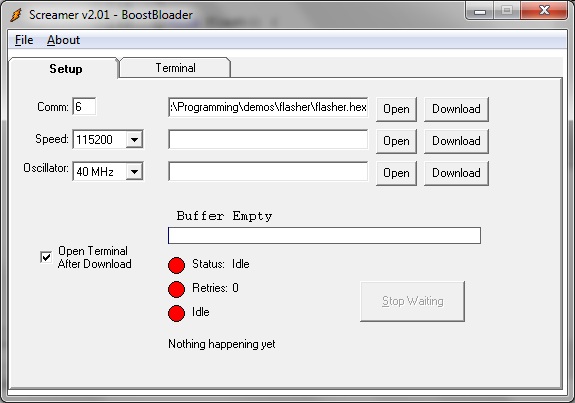
Change the Comm setting to match your com port. Set the speed to 115200 (this is the bit rate we’re going to be programming the PIC at) and change the Oscillator setting to 40Mhz. Even though the 18F2620 has a 10Mhz crystal attached, we’ll be running it at 4 times that rate. Click on the upper-most Open button and find your flasher directory, and the flasher.hex file located in it.
Click the Download button and plug in a power connector to your Olimex board. Screamer should display a downloading progress bar and all being well, your Olimex board LED will start flashing every half a second.
If you want to reprogram your PIC, you can press Download on Screamer, and then hit the Reset button on the Olimex board.
Now you’ve got a platform to develop embedded software on. But it would be pretty nice for the PIC to tell us what it’s up to, don’t you think? Stay tuned for the next tutorial…