GO
Products
News
Tutorials
Custom Design
My Cart
My Account
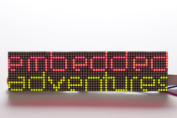
EMBEDDED ADVENTURES:
CONNECT THE WORLD AROUND YOU
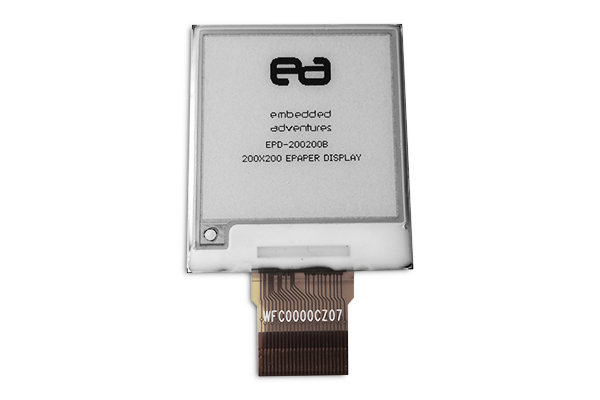
Epaper Displays
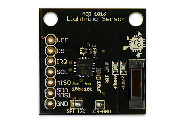
Sensors
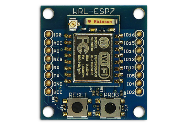
Wireless Modules
Sound
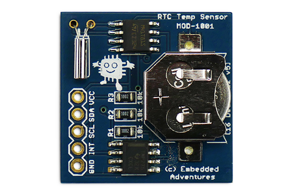
Time
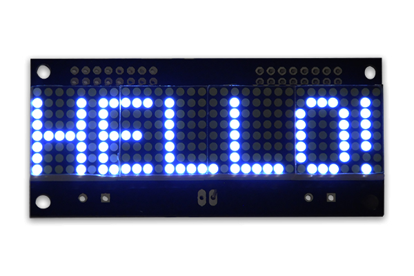
LED Matrix Displays
Tiny LED Matrix Displays
SMRT Pixels
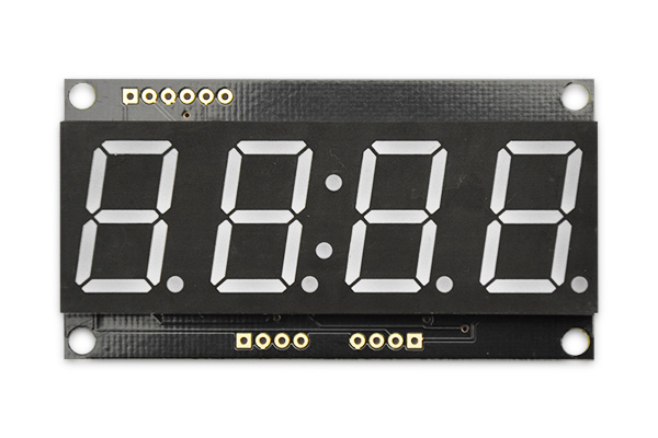
7 Segment LED Displays
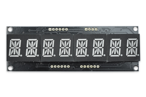
Alphanumeric LED Displays
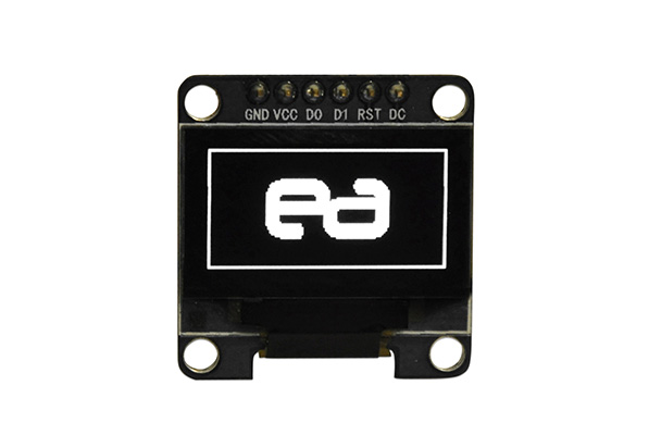
OLED Displays
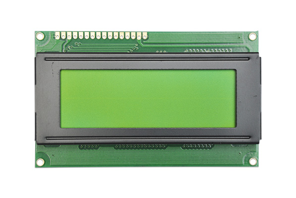
LCD Displays
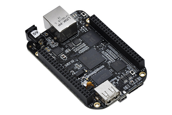
Development Platforms
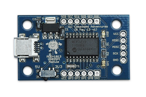
Signal / Protocol Translators
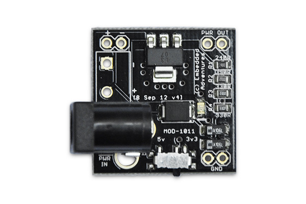
Power Modules
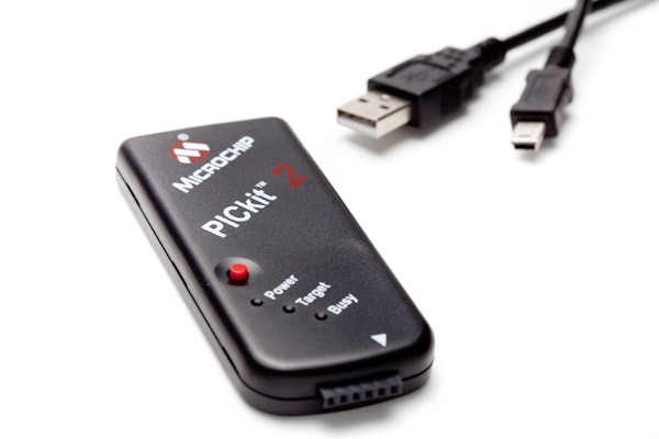
Development Tools
Components
Tutorials
Introduction to Embedded Systems
USB
Capacitors
View All Tutorials
Latest News
Embedded Adventures update
BME280 Arduino Weather project
BME280 weather multi-sensor
View all News stories