EMBEDDED ADVENTURES: CONNECT THE WORLD AROUND YOU
Tutorials in this section:
Let’s dip our toe into the world of microcontrollers. To do that, we’re going to use the emulation environment in SourceBoost to simulate the hardware for us.
Head on over to www.sourceboost.com and download the latest released. It will work perfectly happily for small programs and you can do this for free.
Once you have this installed, download the PicPack library, which can be found in the tutorial section of the EmbeddedAdventures website, under Downloads.
When you’re ready, load up the SourceBoost environment, pull down the Project menu, choose Open, and select “flasher.__c” from the demos\flasher directory, wherever you put the PicPack library.
Hopefully your screen will looking longingly reminiscent of the picture below.
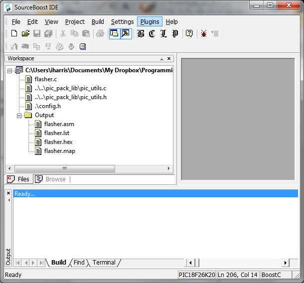
Some quick notes on the environment. Along the left hand side you can see the Workspace. Here’s where you put all the files associated with your project. At the moment we have flasher.c, pic_utils.c, pic_utils.h and config.h. Below in the output folder are some of the files that will get created as part of the compilation process. If you double click on, for example, flasher.c, it will open in the editor window on the right. Along the bottom is the build window which will show you what is happening with your compilation.
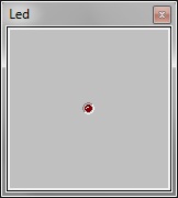
Pull down the Plugins menu, and choose Led. You’ll see a window open up on the right hand side with a single led in it. Right click on the LED and choose configure.
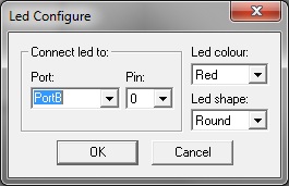
This is where you virtually wire up the LED to a pin on the chip you’re going to simulate in software. Make sure the Port is PortB, the pin is 0, and change it to a red colour. Change it to a round LED too.
Remember that PICs have I/O pins broken up into ports of (up to) 8 pins each. Here we are choosing the B port, pin 0. Physically, the pin is labelled “RB0” on the device pinout diagrams.
Okay, so now we’re going to turn the C program in this project into machine code that the PIC understands. Not only that, but we’re going to actually simulate what the PIC would do if it was presented with this machine code.
Compile the program by pressing F7. Click on the debug button (it looks like a little red bug, which will change to green when you press it). Press F5 to run the program. If you have misplaced the LED window, select it again from the Plugins menu. Check out that flashing LED!
Actually the real hardware runs a lot faster. In this example, the LED would be flashing too fast (every 2ms) to see in real life. In the simulation environment, things take a little longer. Before we get some hardware going, let’s have a look at what this program does. In the workspace window on the left hand side is all the files that are part of the project. Double click on flash.c and you’ll see it in the editor on the right hand side.
/* Flasher!


A good little test program that flashes leds..


*/


#include "pic_utils.h"
Pic_utils.h includes a bunch of handy stuff; you’ll generally want to include it every time. We’ll cover what’s in pic_utils later on.
#define flash_port PORTB

#define flash_pin  0
#defines are great to use wherever and whenever you can. It means that you can make simple hardware changes (like using port a instead of port b) by doing equally simple software changes (changing the #define) instead of having to find every instance of port b when you are referring to your flashing led pin, and changing them.
void interrupt () {
}
PICs have at least one, if not two, interrupt routines that are executed upon certain events happening, like a timer going off or a serial character being received or a pin changing level. We don’t do anything with it here – but I include so that if we’re using a bootloader, everything will be at the right location in memory. More on this later.
void flash() {

	toggle_pin(flash_port, flash_pin);

}
This is where all the action is. We just flip the output of this pin to high if it’s low and low if it’s high every time this function is called. Toggle_pin is a pic_utils routine, which we’ll explore more a little later.
void main() {

	turn_off_analog_inputs();

	make_output(flash_port, flash_pin);

	while (1) {

		flash();
		delay_ms(250);

		delay_ms(250);

	}
}
The main routine has a couple of interesting things in it. Firstly, some ports can be analogue inputs or digital inputs, and by default they start out life when booted as analogue inputs. So this nifty routine fixes that for our purposes. Then we set the flash port / pin combination to be a digital pin (the default, once it’s no longer an analogue input, is a digital input). Not all pins can be an analogue input, but just turning them all into digital pins at the start means we don’t have to do datasheet hunting at this stage of the game.
Finally, in our main loop we flip the led, then wait 2ms before doing it all again. Forever.
Lastly, have a look at config.h.
#pragma CLOCK_FREQ 64000000
This tells the compiler how fast you expect the clock to be running. This is so the linker can generate a “delay” routine for you that matches your clock speed. Delays are really carefully crafted loops. We really only know how long 2ms is by knowing the clock rate and how make clock cycles a given set of instructions take to execute. Here we’re telling the compiler that our PIC will be running at 64Mhz, which in the case of Microchip PIC16 and PIC18 families, means the PIC is running at 16 mips.
The config.h file is the PicPack way of telling the libraries how you would like things to work. It’s where you configure your system, specifying which hardware pins are going to be used for which function and so on. It means we can keep the source code general enough, but you can port it to your hardware configuration just by changing the settings in this file.
So there you have it – your first microcontroller program. Next episode – let’s get the same thing running on real hardware.