EMBEDDED ADVENTURES: CONNECT THE WORLD AROUND YOU
Tutorials in this section:
If you're reading this, then you've probably heard about microcontrollers, or Microchip PICs or Atmel AVRs and want to find out more. Or you've got some sort of electronic problem that might well be more easily solved with a microcontroller rather than standard logic chips. Or you're comfortable writing software but have a different problem that isn't best solved by a full-scale PC.
In any of these cases, you're in the right place. First though, let's take an overview of a typical microcontroller and what it's capable of. For this example, we're going to use the PIC18F2620, a chip that's used in the Embedded Adventures LED Display Driver (PLT-1001). The key to understanding any of these parts in detail is the datasheet - but we're going to pull out some key functionality to help give you an easy overview.
Instructions
The whole point of a microcontroller is to be able to run software. The instruction set of these devices is simple - there are only 75 standard instructions - and in the past many hardcore microcontroller programmers have insisted that to get the best of out a device, you need to program it in assembler language. These days, C compilers are more efficient, the chips themselves have far more memory and run at a faster speed - so there's really not much point doing anything in assembler unless you really have to. Sometimes you do, but really not very often.
The libraries available on this website and the examples used in this tutorial are all based on the Sourceboost compiler. We chose this one as it produces very fast, tight code, is well supported by its authors and is simple to get started in. There are other compilers around (including one from Microchip themselves) and you can happily port this code to your preferred compiler should you wish.
So how many instructions can you have in a chip? Even though these are “8 bit” devices, instructions are 16 bits wide. The PIC18F2620 has 64K of flash memory to store instructions, resulting in a total number of instructions amounting to 32,768. That doesn't sound like a lot of memory compared to the laptop or desktop computer you're using to read this on - but in the microcontroller world, that's plenty of memory to get some quite interesting jobs done.
Memory
These instructions are stored in “flash” memory. This can, in the case of the 18F2620, be erase and rewritten at least 10,000 times. This is also known as program memory, since, unsurprisingly, this is where your program goes.
RAM available on this chip is 3,968 bytes, which again seems an incredibly small amount, but is generally plenty for the tasks we'll be using these chips for.
Some microcontrollers have another type of memory as well - EEPROM, Electrically Erasable Programmable Read Only Memory. At least, that's what it's called. These days it is typically just a different type of flash memory, one that is better suited to being changed more frequently. As such, it is smaller (since its expensive) but has a higher number of erase/rewrite cycles. Our 18F2620 has 1,024 bytes of EEPROM, and is rated for 1,000,000 erase/rewrites.
There are two other points that are important here. The first is that the PIC range has what is described as “modified Harvard architecture”. This means that the flash program memory and the data RAM are accessible via different busses, so in fact they can be accessed at the same time. Program memory and RAM are not one big contiguous block - there is a location 0 in RAM and a location 0 in program memory. The same with EEPROM memory, it has its own address block starting at 0 and going to 1023.
Peripherals
Microcontrollers have a host of functionality built into them. Here are some examples of things you'll typically find available to you. Don't worry too much about the details at this stage, this section is just to give you a flavour of the functionality available.
Digital I/O
You can output 0 (0V) or 1 (Vdd, typically 5V). Or you can read an input in the same way. The I/O itself is clumped into a “port”, where each port has up to 8 pins. Ports are labelled from A upwards. Of course, the more actual physical pins a chip has, the more ports it has available for you to use. The 18F2620 has 28 pins and has ports A, B, C and one pin available in port E. For the most part, individual pins can be used as inputs or outputs, or switched between the two at any point.
I/O is the bread and butter of microcontrollers. You can use these pins to turn LEDs on and off, read the input of a press-button switch, communicated with other devices (temperature sensors, LED Panels or Real Time Clocks).
ADC
You can convert an analogue input voltage to a digital number. The 18F2620 has a 10 bit ADC module. That is, 0V will convert as 0 and 5V will convert to 1023 and 2.5V will convert to 511. There is only one ADC module, but you can choose any one of 10 pins to be converted to digital and change which pin you select at any time.
You might have a humidity sensor that outputs a voltage proportional to the humidity. Or perhaps a microphone connected through an OpAmp. In these cases, the ADC is your way of finding out what's happening in the analogue world.
Serial communications
You're probably familiar with RS232 or "serial" communications. TTL or UART serial is an asynchronous serial connection that it uses 0V for 0 and Vdd (5V in our case) for 1. RS232 which uses a negative voltage as 1 and a positive voltage as 0. There is a serial module available to you to handle asynchronous communications, and it's given the grand name of EUSART (Enhanced Universal Synchronous Asynchronous Receiver Transmitter). Everyone calls it a UART in real life. The module can talk asynchronous serial (receive and transmit lines) or synchronous serial (receive, transmit and clock lines).
There are other serial communications mechanisms as well, ones that are designed for chips to talk to each other. I2C is one (Inter Integrated Circuit) - which uses two lines to communicate bi-directionally. SPI is another, it uses dedicated input, output, clock and chip select lines. Both of these serial buss communication methods are available in the Master Synchronous Serial Port (MSSP) module.
Timers
Timers are an important building block. How long has the user held a key down? Is it time to retransmit a new packet across the wireless network? Is it time to refresh the display?
Capture/Compare/PWM (CCP)
The CCP module does things with timers. The capture function tells you the value of a timer when an input changes a particular way. Compare function can do a variety of things when a timer gets to a certain value (such as reading an analogue input or flipping the value of an I/O pin). The PWM function allows for pulse width modulation. This allows for the switching on and off of a pin at a particular frequency, but also gives you the ability to specify the proportion of the frequency the pin is on and the proportion that it is off. At 100%, a LED is fully on. At 50%, the LED is half as bright. At 25%, the LED is even dimmer.
Other peripherals
There are other peripherals available as well - but these are the main ones you'll bump into.
Power
All devices need power. Power is supplied to the Microchip range via the Vss pin (ground) and the Vdd pin (positive supply). This is their convention (you might be more familiar with Vcc being the positive supply), so we're going to use it in these examples.
Clocking
In order to make the microcontroller execute instructions, you need to poke it. Often. In fact, all the time. There are a bunch of different ways of doing this, from using quartz crystals to using an internal oscillator. These different ways have tradeoffs for performance vs current consumption vs pin usuage. For the most part, the Embedded Adventures kits use crystal oscillators which give very accurate timing but sacrifice two I/O pins to the cause.
Where are all these pins anyway?
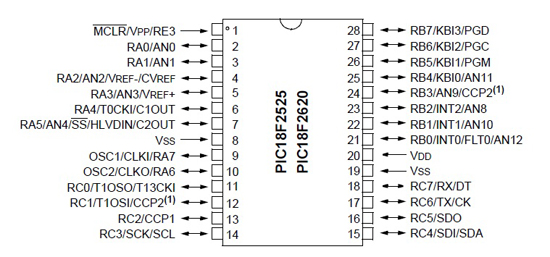
With all these peripherals and I/O pins, how do they all fit onto a 28 pin device? The answer is: they don't. There are more capabilities than pins available to house them. So there's a double up between modules. The following diagram makes that clear. Have a look at pin 2. It's port A, pin 0, and also ANalogue input 0. Pin 7 has five different functions available on it. When you're building your circuit, you need to make some decisions about which functionality is important to you and configure your microcontroller to suit. That's an important part of any microcontroller program - configuring the device and its peripheral modules to do your bidding.
Where to from here?
The first step we're going to take is not in hardware - it's in software. We're going to use the SourceBoost compiler and IDE to create your first microcontroller program without even getting the soldering iron warmed up.