EMBEDDED ADVENTURES: CONNECT THE WORLD AROUND YOU
Tutorials in this section:
Making the PLT-1001 – Kit version A
June 2010
This document version 1.0
Components
First, check you have all the components for the PLT-1001. You can do this by emptying your kit contents onto a white sheet of paper. We really do ask that you do this carefully – there are some small components in this kit and we don’t want you to lose any.
|
Name |
Qty |
Component |
Value |
|
Q1 |
1 |
Crystal |
32.768Khz (small silver tube) |
|
Q2 |
1 |
Crystal |
10Mhz |
|
LED1 |
3 |
LED |
Red |
|
+5V/Gnd/Supply |
3 |
Screw terminal |
2-way |
|
S1 |
1 |
Switch |
Short button |
|
D1 |
1 |
Diode |
1N4148 |
|
C1 C4 |
2 |
Capacitor |
100nF (labelled 104) |
|
C2 C3 |
2 |
Capacitor |
22pF (labelled 22) |
|
C6 |
1 |
Capacitor |
10uF Electrolytic (blue labelled 10u) |
|
C7 |
1 |
Capacitor |
10uF Tantalum (orange labelled 10) |
|
R1 R3 - R7 |
6 |
Resistor |
10k (Brown Black Orange Gold) |
|
R2 |
1 |
Resistor |
330R (Orange Orange Brown Gold) |
|
U1 |
1 |
Microcontroller |
PIC18F2620 |
|
U2 |
1 |
Real Time Clock |
M41T81S |
|
U3 |
1 |
Temperature Sensor |
TMP75 |
|
U4 |
1 |
Level translator |
TXS0104E |
|
U5 |
1 |
3.3V regulator |
Labelled “17-33” |
|
B1 |
1 |
Battery |
CR2032 with solder leads |
Male breakaway header for ICSP, Serial, LED panel connections
Solder wick
Printed Circuit Board (PCB)
What you’ll need
A soldering iron. There is a small amount of surface mount soldering in this kit. You don’t actually need one with a 0.2mm tip, or even anything like it. A “normal” soldering iron you’d happily use for through-hole components will be fine. It’s a little easier with a thinner tip – you can place heat more accurately – but that actually brings some more challenges, since most irons with a thinner tip don’t actually get all that hot right at the tip, so you end up using the side of the tip anyway. The tip does need to be shiny and hold solder on it when you melt solder on to it.
You’ll need a wet sponge to clean the tip with regularly.
Wire cutters. To clip the ends of components after they’ve been soldered.
A well-ventilated area in which to carry out your work. Even if you’re doing the right thing and using lead-free solder, we recommend working in an area with plenty of air flow.
A multi-meter is always handy as you hook things up.
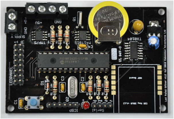
Board layout
Surface Mount Components
The first thing to solder is the surface mount components, simply because it’s much easier before all the other components are fixed in place.
Start with the TMP75. Apply a little solder to one pad on the printed circuit board where the TMP75 is to go, such as pin 1 (indicated by a dot).
Using tweezers or similar, place the TMP75 chip on the PCB. Note that the TMP75 may indicate the end of the chip where pin 1 is by a bar instead of the more usual dot. So the end with the bar goes towards the outside of the board. While holding the TMP75 in place, head the solder you have already applied with your soldering iron so it becomes molten. Use the tweezers to arrange the TMP75 in the right place at the centre of the SMD pads. If you don’t get it right first go, take your time and simply re-head the pad until you have it placed correctly. Make sure the pins are centred in the middle of the pad and the chip itself has about the same amount of pad exposed on either side.
Moving to a pin on the other side and other end of the TMP75, clean your iron tip on a wet sponge and then apply a small amount of solder to the pin and pad. It will need a moment for the solder to “take” to the pad. Don’t worry too much if you bridge two pins with solder, so long as they are both affixed to their pad. Keep doing this until you have all pins soldered down.
Now inspect your chip carefully to see if you have in fact bridged any pins. If you have, first clean you iron tip, then try melting the solder in between the pins with your iron tip, then sliding the iron back down the pins away from the chip. If that doesn’t clear it, it’s time for one of the greatest inventions known to soldering: solder wick.
We’ve included some in the kit. Make sure the wick has a nice clean end, cutting it if necessary. Holding the wick with one hand and your iron with the other, place the end of the wick on the pins you need to clear. Place the iron on the wick so the wick is sandwiched between the iron and the pins. Holding it there for a moment, you should find that the solder melts and the wick soaks it up. As you remove the solder, don’t forget to take the wick with it – otherwise it will end up stuck to the pins. Now check the pins – you can add more solder now if you wish, but you’ll probably find that the pins are actually still soldered down.
Continue until you have removed all extraneous solder. Don’t forget to clean your iron tip and make sure you cut off the used wick before you do the next one. If you find nothing’s happening, you have probably forgotten to trip your wick.
Use the same procedure with the M41T81S real time clock. ST uses its logo to represent pin 1 – so the side with the ST logo goes to the outside of the board.
You’re getting good at this now. After doing a couple of surface mounted chips, it will all seem straight forward. Armed with solder wick, there’s not too much you can’t fix.
Next up is the TXS0104E. It has a bar along one side of the chip, this goes in the direction of the dot on the PCB layout (that is, towards the centre of the board).
Finally, the voltage regulator. Easy, this one! Make sure you apply plenty of solder to the tab at the back of the chip – this is used as a heat sink as well as an electrical connection.
If you’re using an MRF24J40MB module, now’s good time to solder it as well using the same process. By comparison it’s a piece of cake with such relatively enormous “pins” and pads. You can solder it later if you don’t have a module to hand.
Resistors
Resistors R1, R3, R4, R5, R6 and R7 are 10k Ohms. They’re coloured Brown Black Orange Gold. Bend them into shape and solder them on the other side. Clip the leads when you’re done.
Resistor R2 is 330 Ohms, indicated by the colours Orange Orange Brown Gold. Solder them next and clip.
Resistors can go either way around, although some people like to line them up so the gold bands are all on the same side.
Diode
Diode D1 is a 1N4148. Bend into shape, solder and clip, keeping the stripe on the diode the same direction as the one on the PCB (that is, towards the PIC).
Capacitors
C2 and C3 are 22pF capacitors. They’re the smaller ones – and you’ll notice they’re marked with ‘22’ on them in very small print. Solder them next; they go next to where the crystal goes. They can go either way around.
C1 and C4 are 100nF bypass capacitors, marked ‘104’. Again, they can go either way around.
C7 is a blue 10uF capacitor. It has minus signs on the body to indicate the negative lead, and you’ll notice the positive lead (the other one) is longer. Make sure the positive lead goes in the + hole.
C6 is a tantalum capacitor that looks like a orange blob. On the face with text on it, you’ll see a line with a + marking. That same leg, which is the positive one, is longer. Pop it into the spot for C6 near the battery making sure the positive lead is in the + hole.
Crystals
The 10Mhz crystal is next. Make sure the crystal has ‘10’ or ’10.000’ marked on it and solder it in the spot for it next to C2 and C3.
The 32.768KHz keeps the real time clock humming along. It’s called a watch crystal, and it looks like a tiny silver tube with two small wires poking out the end. When you insert it, make sure that you don’t twist the wires together. Also, don’t push it all the way in when you solder it – leave enough slack so you can bend it over flush with the board on the top side, just like the image on the PCB.
Crystals can go either way around.
LED
You have one LED available to you. Use it wisely. Make sure the long lead goes in the hole marked with “+”, towards the centre of the board. It won’t work the other way around.
Switch
It’s time for the switch now. The switch will naturally fit only one of two ways, and either is fine. You’ll notice there’s plenty of give in the PCB holes for them. Suspend the switch in place, soldering one leg, make sure it’s flat, then return to the other legs. As always, it’s best if you use one pin to anchor and position it. A good trick here is using blu-tack to hold it in place.
PIC socket
The PIC isn’t soldered directly onto the board; instead, it has a socket to go in. The socket has a small notch in one end – place that the same way as the PCB picture, that is, with the notch facing towards the LED Panel connector.
Headers
Finally, it’s time to solder the male headers in place. Clip the breakaway header to the right length. Solder one pin and then check the header you’re soldering is actually perpendicular to the board. Melt the solder and adjust as necessary. Once you’re satisfied, solder the rest of the pins. Repositioning after one pin is easy. After solder two or more...it’s pretty much impossible. You have headers for Serial connections, ICSP programming and connecting the LED panel.
Battery
The battery only goes one way around. You might find blu-tack is handy in holding it in place. Why are we soldering a battery in place? What happens if you want to replace it? Actually the battery only supplies backup power to the RTC so the time continues even if you remove the main power supply. We’ve secured such excellent batteries that it will continue to power the RTC until the end of the universe, or about 10 years, whichever occurs first.
PIC insertion
Place the PIC into the socket with the notch in the PIC matching the notch in the socket. The notch goes towards the LED panel connector. You may need to gently bend the pins inwards to get it to fit. Do this by rolling the PIC gently on a flat surface. It will need a gentle push into the socket but do check that all the pins are actually lined up to go into the socket.
Final checks
Have a good look at the board. Look for solder bridges on the surface mount devices and check for nice shiny solder connections on the back of the board. Check you’ve actually soldered everything too. Go back and check the polarity of the capacitors and the diode. We know you’ve made a thousand kits before, but everyone makes mistakes and we want you to have a great experience first time. You can check the polarity of the LED by looking at the metal inside the LED casing – the larger triangular piece of metal is on the negative lead’s side.
Initial testing
Time to check it actually works. All our PICs come with the BoostBloader pre-loaded. So the first thing that should happen after applying power is that LED1 (furthest from the MRF module), connected to RA0, should flash. This is a very good sign that all is good in the world.
Following that, the PIC18F2620 runs a diagnostic program that checks the temperature, the time on the RTC and if it can communicate with the MRF module. It prints all this out at 9600bps UART serial via the serial connection. It will also rapidly flash the LED.
When applying power, make sure you get it round the right way. Ground goes to ‘GND’, 5V or so goes to ‘+5v’. Double check your supply with a multi-meter if you are any way unsure. This also confirms your supply is working.
If it doesn’t work:
- Have you got D1 round the right way?
- Are the capacitors around the right way?
- Is the LED round the right way?
- Are there shorts on any of the surface mount pins?
Actually, there’s not much that can go wrong with this kit so long as your soldering is okay and you put the components around the right way. We don’t really expect you to have any problems here. Email us at support@embeddedadventures.com if you’re really stuck.
The software provided on the PIC does not make anything at all happen on a LED Panel, even if you connect one up. To do that, you’ll need to update the software.
Updating software
Fine, you’ve got a LED flash. What next? Crank up your copy of SourceBoost, compile draw_ea_ldp6416 (in the demos directory of where ever you’ve put the PicPack library) or draw_ea_ldp6432 depending on the LED Display you have.
Connect your TTL-Serial connection to the Tx/Rx and ground connections supplied on board, noting that you’ll need to swap the Tx/Rx connections (TX/out from the board is Rx/in with respect to your TTL-Serial board).
Now you’ll be able to use the venerable Screamer application (found in the PicPack collection) to send the .hex file produced by SourceBoost to your board. Select your Com port, set the Speed to 115200, and Oscillator to 40Mhz (this is the speed the chip is running at, 4 x 10Mhz). Find your .hex file by pressing Open, then press the nearby Download button to transfer the .hex to the PIC. The first time you do this you may need to press the reset button on the PLT-1001 to get them to sync up. After that, it should happen just by pressing Download. Connect up your LED Display Panel and you should see the Draw demo run though its checks.
Note: The PLT-1001 provides screw terminals for supplying power to your LED Display, however, the PCB is only able to supply about 1 amp. If your supply provides more than this, you’ll need to connect your LED panel directly to your supply using wiring provided with your panel or other wiring with the appropriate current rating.
For more information about bootloading and BoostBloader, see the Tutorials section on the website.
After that – it’s up to you! Do send us in any feedback on making our using this kit to feedback@embeddedadventures.com. If you’ve had problems, please let us know so we can improve our kits and instructions. If you’ve had fun, please tell us about what you’ve made and do send us pictures of your LED Display Panels all it up!