Page 12
28 Mar 12
Many people think that microcomputers are complex digital electronic devices with an embedded circuit board and software code that is way beyond the scope of their understanding. They may know how to operate a device through its external user-defined functions, but they have no idea how it actually works internally.
Even though the software code and circuit components do seem complex in a digital circuit, the fundamental processes that take place inside are actually just based on a simple base-two number system, where a digit can either be a '0' or '1'.
This would even be simpler than the base-ten number system that is used normally in everyday life, where the digits can be '0' to '9'. This base-two system is known as a 'binary' number system, and a '0' or '1' can also be thought of as being either 'on' or 'off'.
What makes the computers complex is the vast amount of '0's and '1's stored inside of it and the various processes of manipulating these '0's and ‘1’s through hardware logic or software logic.
Even this can be simplified by the fact that as a binary number becomes an input to a hardware or software logic structure, another binary number will appear on the output based on the function built into the logic structure. For example, an AND gate will have a logic '1' output only when both inputs are also '1'; otherwise the output is '0'. All the circuitry inside a microcontroller chip can actually be built by using thousands of these little integrated AND gates along with another simple gate called an 'inverter', which has one output that is always the opposite of its input.
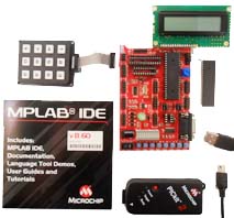
Kanda – Embedded Results Ltd uses these simplified concepts with a new kind of training program for learning basic embedded system development skills. They have just come out with a new PIC kit where even a beginner without any prior knowledge of electronics or programming can learn the fundamentals of developing and building a customized microcontroller-based circuit. The training program starts out by discussing the binary number system as described here, and then moves on to learning about the structure of a microcontroller. Then it progresses on to teaching assembly language before finally discussing the C language.
The kit is designed for Microchip's PIC16F and PIC18F series of microcontrollers, and includes a PICkit2 debugger and programmer which connect to the Kanda PIC development board.
This would allow single stepping through the code (either assembly or C) so the circuit can be analyzed one step at a time. Microchip’s MPLAB development software is used with the programmer and debugger and these are learned about as needed in the final stages of the training program. MPLAB is a powerful tool, as it contains a built in editor, assembler, C compiler, and simulator. It can also load the PIC microcontroller with the finished code.
Many code samples are provided to assist in programming as a programmer can quickly develop input/output software routines based on these examples.
The course starts by covering simple topics like reading the inputs from switches and energizing outputs for LEDs, and then moves on to inputting from keypads, and outputting to seven-segment displays and LCDs. Analog to Digital Conversion is covered also, so a circuit can be used with analog devices. Designers would be able to quickly develop instrumentation and robotics projects.
Everything needed for PIC training is included right in the package. There are switches, LEDs, ADC, EEPROM socket, and a UART interface built into the board, and there is also an LCD module and a keypad included with the kit. The PIC board supports most 8, 14, 20, 28 and 40-pin PIC microcontrollers in PIC16F and PIC18F families, and allows easy access to all peripheral functions.
27 Mar 2012
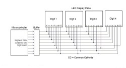
Staff writer James Reinholm introduces a neat way of multiplexing LED displays.
Click to enlarge
It uses a very clever trick to allow you to control all the digits of multiple displays without requiring seperate lines to select the digit to be lit, as is typical with multiplexing solutions.
25 March 2012
Embedded Adventurer Jez Thomas has written a great tutorial and sample code that will help you get the Arduino controlling the 14 segment 8 digit DSP-0801 display.
Thanks for sharing, Jez!
28 Feb 12
Microchip and Matrix combined their efforts with element14, a collaborative global electronics community, to introduce a new concept in programming and electronic design by using a hands-on approach. The new PIC18 Flowcode Development Kit makes it simple and easy by using the graphical design features of Flowcode, an advanced programming language for microcontrollers.
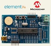
The module is based on Microchip's PIC18F26J50 8-bit MCU, which is designed for low power, cost-effective, high speed USB 2.0 applications, and offers a high degree of peripheral interface flexibility. A Peripheral Pin Select can be used to map peripherals to I/O pins and the module also features a built in CTMU capacitor touch sensor module for capacitive touch user interfaces.
A potentiometer, several break-out pins, a temperature sensor, and other sensors are also included with the kit to provide data for the data manipulation by the programmer. The low power mode selection also includes a new deep sleep mode for extremely low power applications. There is a professional edition available which includes driver interfaces for many other devices, including LCDs, keypads, and seven segment displays. This edition also features PWM along with several communication protocols, such as I2C, SPI, RS-232, Zigbee and TCP/IP.
Flowcode 4 is considered to be one of the world’s most advanced graphical programming languages for microcontrollers. Complex electronic systems can be designed in minutes even by those with little to no programming experience. Flowcode is normally used with Microchips PICkit programmer, but can also work for third party programmers, and it is also compatible with the HI-TECH C compiler. Flowcode supports microcontrollers in the PIC12, PIC16, PIC18, PIC24 and dsPIC series.
This is one of the first microcontroller development kits available that is not designed only for engineers, but can be used by complete novices. The kit features the PIC18F26J50-EVK Board, USB cable, and the "Lite" version of Flowcode 4.
21 Feb 2012
Any application that relies on a harvestable ambient power source requires careful power management in order to successfully capture the few microwatts of ambient power and store it in an energy storage device where power can be used when needed.
The ambient power source can only supply power in the order of tens of microwatts, while an electronic device usually consumes power in the order of milliwatts. Therefore, the harvested energy must be stored whenever possible, and kept ready to use when needed.
The electronic device must operate at a duty cycle that does not exceed the energy storage. Sometimes this duty cycle can be as low as 0.5%. If for some reason, the ambient power source stops supplying power, the device can usually continue to operate for about 100 hours at the programmed duty cycle, assuming the back-up battery is charged. The power management software should be able to detect this loss of power and prepare for shutdown and display a shutdown message, store data in nonvolatile memory, and other important tasks.
One common form of ambient energy is mechanical vibration energy, which can be caused by motors running, airflow across a fan blade, or even by a moving vehicle. A piezoelectric transducer can be used to convert these forms of vibration energy into electrical energy, which can in turn be stored in an energy reservoir and also be used to power circuitry.
Linear Technology and Energy Micro from Norway have combined their expertise in creating the new EFM Starter Kit, which is a development kit that uses Linear Technology's LTC3588 piezoelectric energy harvesting power supply and Energy Micro's ARM Cortex-M3 enabled EFM32 Gecko microcontroller. This device is a wireless sensor node that acquires data from a 3-axis accelerometer and then transmits it through a Zigbee RF transceiver.
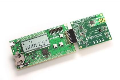
The starter kit’s micro-power 32-bit MCU has a software algorithm that makes certain power measurements at regular intervals to ensure that total circuit consumption stays below harvested energy levels by adjusting the duty cycle and other parameters.
The energy harvested from a piezoelectric transducer is stored on a capacitor bank for later consumption by the accelerometer and radio according to the MCU's optimized sequencing software. The MCU spends the majority of its time in sleep mode until woken by the LTC3588's 'power good' signal.
To manage the energy harvesting and the distribution of energy, the LTC 3588-1 piezoelectric energy harvesting power supply integrates a low loss internal bridge rectifier with a synchronous step-down DC/DC converter. It is designed with an efficient energy harvesting algorithm to collect and store energy from high impedance piezoelectric elements.
The device enters an ultralow quiescent current under-voltage lockout (UVLO) mode with a wide hysteresis window which allows charge to accumulate on an input capacitor until the internal buck converter can efficiently transfer a portion of the stored charge to the output.
Four output voltages, 1.8V, 2.5V, 3.3V and 3.6V, are pin selectable with up to 100mA of continuous output current. The output capacitor may be sized to provide higher output current bursts. An input protective shunt set at 20V enables greater energy storage for a given amount of input capacitance.
20 Feb 2012
The Microstick II tool from Microchip is possibly the cheapest starter kit available for developing and evaluating 16-bit and 32-bit PIC MCUs, and 16-bit DSCs.
This flexible tool provides all the basic features needed to get started with these MCUs and DSCs, and includes a USB interface, an integrated programmer and debugger, a user LED, a reset button, and a DUT socket for switching devices. Since the device is USB powered, no battery or external power source would be required.
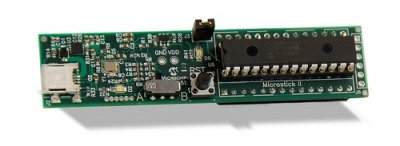
These features are all contained in a very small package that is about the size of a stick of gum (about 20 x76mm), and makes it extremely easy to start developing with MCUs and DSCs. In addition, two 1x14 header pins (0.025”) are included in the kit for using with a prototype board, so designers can easily plug the Microstick II tool into a standard prototyping board for experimenting with external circuitry, and also provides space for jumper wires.
There are 19 flexible I/O pins available that should have enough interface capability for their new application ideas.
There is easy access to all I/O features included on the device. One great feature is that many of the I/O pins are configurable with Microchip’s Peripheral Pin Select (PPS) so the internal hardware can be mapped to any of the pins at any time. For example, it is possible to connect an I2C port which uses the same set of pins that are used for an ADC input.
The Microstick II includes two types of PIC24 chips, a PIC32 chip, and a dsPIC33 digital signal processing chip. The kit will support any of the dsPIC33s in a SPDIP package, and any of Microchip’s 16- or 32-bit MCUs with a 28-pin SPDIP package that would match the power and debugger/programmer interface pins shown on the enclosed schematic. This is somewhat limited compared to a PICKit3, but is much cheaper.
Free demo code is provided, along with installation instructions and board schematic. Most of the code samples are written in the C programming language and requires a C compiler to be installed. A free C compiler is available, along with the free MPLAB Integrated Development Environment (IDE) software. The kit is designed to be used with MPLAB IDE, and this tool provides assembler tools for development, so the C compiler wouldn’t be needed if only assembly language is used to program the code.
A designer can buy several types of MCUs and DSCs in addition to what is supplied in the kit which can plug into the Microstick II, and each one can be tried out in his design to find the best possible solution. Some designers prefer to use UART as a programming port instead of USB, and it would be possible to use UART in the Microstick II, but external level shifter circuitry would have to be added to this to connect it to the PC or other programming source.

